|
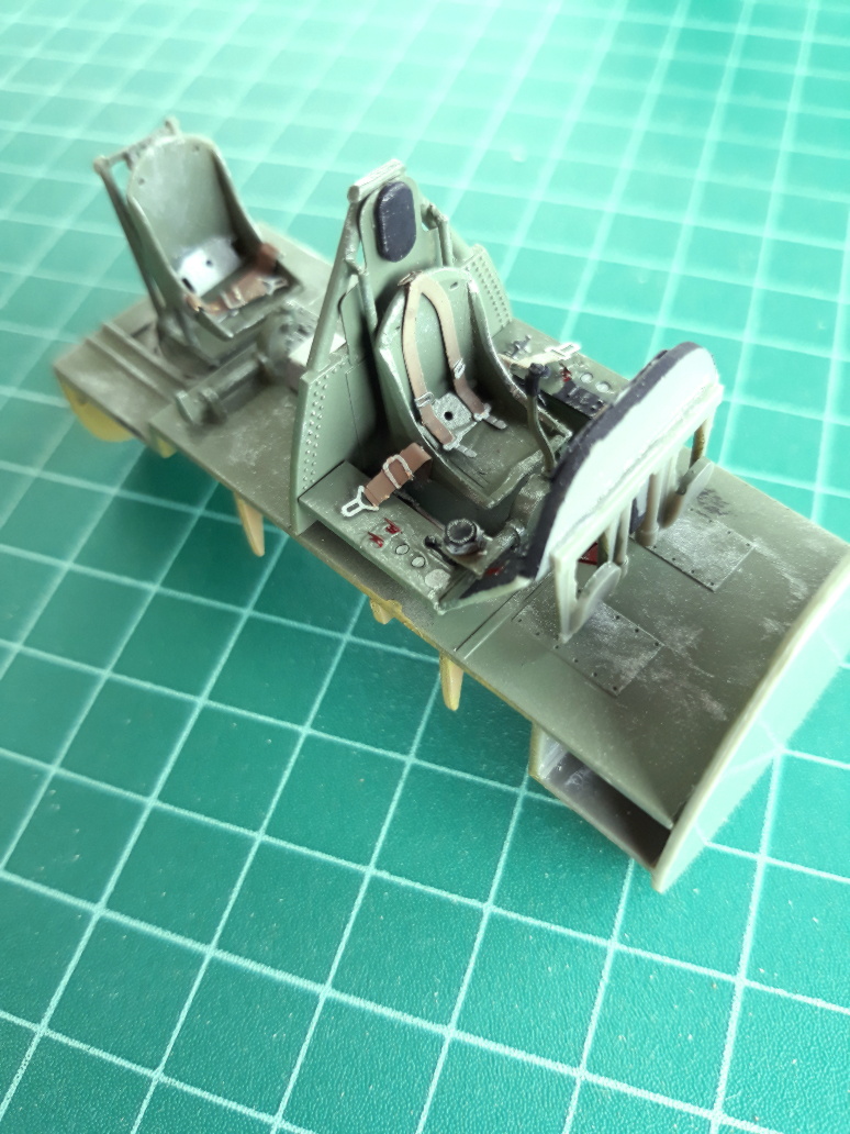
I built the pilot's and observer's cockpit areas pretty much as in the kit instructions. The only part I added was the observer's control column which is not included. I fitted it in its stowed position on the port side of his cockpit. I had some trouble with the smaller etched parts and some difficulty in interpreting the kit instructions as to exact placement of parts. Fortunately, I had a manual and some photos handy which helped. I would suggest that some consideration is given to not attaching some of the smaller parts until you are about to attach the cockpit transparencies, as these are easily knocked off or damaged when handling the model.
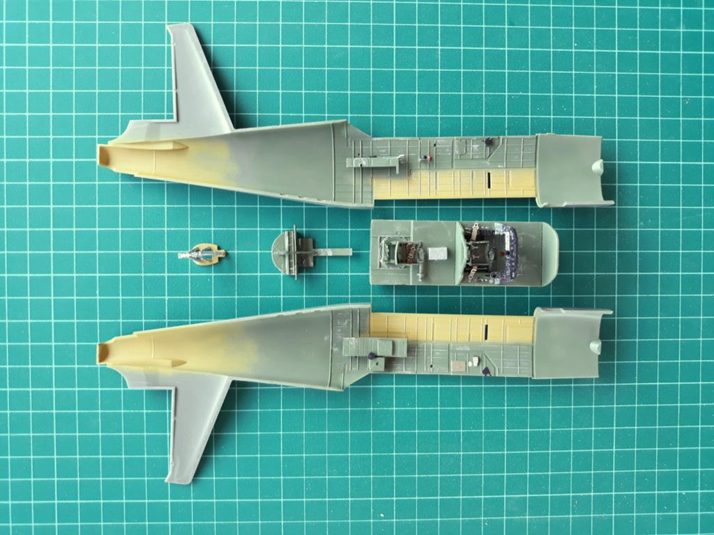

I assembled the bomb bay but left off the door brackets and actuating rams at this time. These would go on when I was ready to fit the bomb bay doors after I had attached the wings and detailed the bomb bay. I would also suggest that you do not fit part K43, the tail wheel yoke, until very late in the assembly process, as it is very easily broken off. I added some plumbing, wires and other fixtures to the bomb bay to try and get it to appear 'busy'. The photos I have do not always accord with what Dora Wings has given so I modified accordingly. In the end it looked OK, but still basic.
I then closed up the fuselage. Before I added the top dorsal section and firewall, (parts F17 and A4), I added the internal ducting at the oil cooler exit, drilled out the vent in the forward part of the dorsal section, and modified the instrument panel coaming so I could fit the armour glass. I also added the N-3 gun sight reflector glass, attached to the rear of the windscreen and the internal armour plate glass fitted above the modified instrument panel coaming.
Externally the fuselage could do with a few improvements. Dora Wings have missed the fairing that is fitted on the starboard side just below the gunner's cockpit. It is a simple job to add this. On the ventral fuselage just aft of the gunner's position are the fairlead for trailing antenna and what I think is the venturi outlet for the gunner's relief tube. On the forward fuselage, between the oil cooler exit and the bomb bay are a couple of hydraulic system vent tubes.

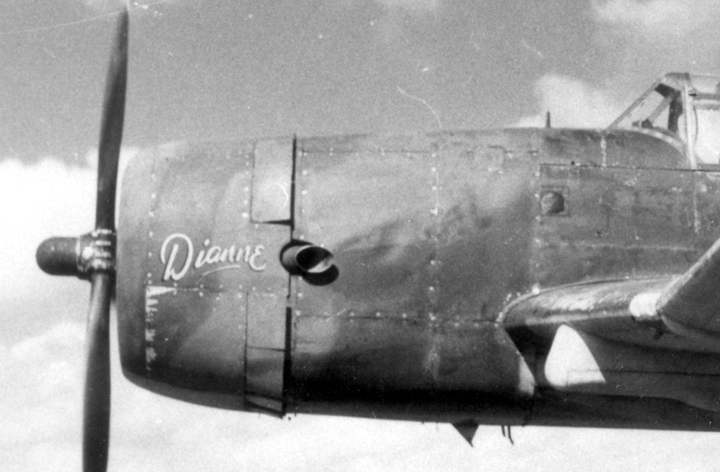
Next, I turned my attention to the engine cowling. As you can see from the photos below there is a distinct difference in shape and depth between the aircraft engine cowling nose ring on the left and the kit part below. In my opinion, this needed correcting, (I did say I was anal re shapes).

First, I assembled and painted the engine, and glued it to the front of the cooling air baffle. (Note that this is not the firewall, which is further aft, at the rear of the accessories bays. On the actual aircraft this baffle is just aluminium alloy sheet, but it has been turned into a nice substantial bulkhead on Dora Wings' model, for mounting the engine).
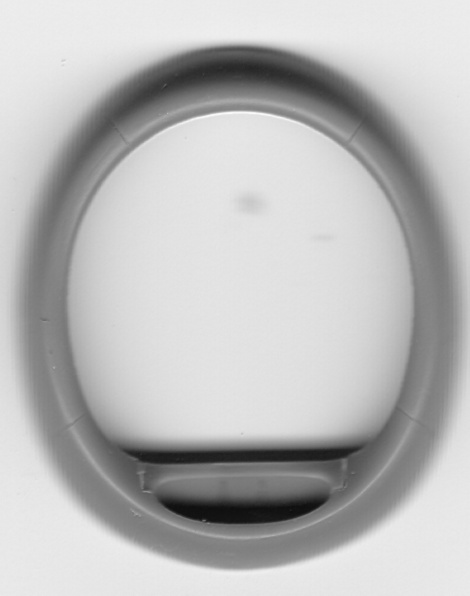
I took a horizontal slice out of the nose ring, (part J15), and re-joined the pieces to get a more circular shape. Then I cut the front cowling side panels, (parts J22 and J23), horizontally just below the extensions for the exhaust ports. I then attached the upper sections of these cowling side panels to the cowling nose ring and, then the combined unit to the fuselage. Some filing of the engine was required to get them to sit properly. The last stage was to mark and cut the lower sections of the side cowling panels that I had removed earlier, so that they now fitted into the lower cowling space and mated with the nose ring and the upper sections of the cowling side panels. This turned out to be remarkably easy and gave the 'upsweep, of the lower fuselage line into the nose ring that I wanted.
It was then a matter of getting to work with a large file and working away at correcting the fuselage cross section on the top and bottom of the fuselage, back to the windscreen / bomb bay. Fortunately the plastic is quite thick in this area and something more closely resembling the shape of the Vengeance can be achieved, albeit at the expense of a lot of surface detail. This was restored with a bit of careful work with a scriber, and some filler where required.
I piked out when I came to trying to fit Dora Wings' etched metal pieces for the cowl cooling flaps. It was probably possible if I had wanted to model the flaps closed but, being pig-headed, I decided that I wanted to have them open. The geometry of taking flat sheets and cutting and bending them so that they mated with the cowling was going to be complex, so I decided to raid the spares box. I came up with some cowl flaps that I think were spares from a Tamiya P-47 which, with a little cutting, filling and scribing, would do the job.
I was not impressed with the two part engine exhausts in the kit and I replaced them with thinned down plastic tube.
Wings:
First, I fitted the etched metal dive brakes into their recesses in the wings. This was relatively easy as Dora Wings had done a good job with the wing recesses and they fitted nicely. Phew! I had expected trouble with that.
Steps 43 and 45 on the instruction sheet show the assembly of the parts that go to make up the wheel wells. Once again, the etched metal bits can be a bit awkward and care is needed to make sure all runners are filed off so they fit correctly in the scribed locations. I found it helped to run the pointy end of a scalpel blade through these locating grooves to widen them slightly. I would also suggest that parts F1 and F6 be fitted first, before building up the wheel wells.
I elected to add some representation of the plumbing and electrical wiring that runs through the wheel wells. With actuators forward of, and flaps aft of, the wheel wells, all this plumbing has to pass through the wells themselves. Then I closed up the upper and lower wing halves. I fitted the fairings for the undercarriage legs and added a little extra in the form of the up-locks on the wing lower surface. The landing lamps and navigation lights were also fitted at this time.
Then I made a big mistake. Initially, I got confused with relating some parts with the part numbers in the instructions. It may have been brain fade on my part, but I think Dora Wings got a couple of the part numbers wrong. After I sorted that out, I glued the upper and lower sections of the flaps and ailerons together. When I tried to offer them up to the wings I found they were too thin! Lots of filler was required and more surface detail lost. I don't know why Dora Wings chose to mould these parts separately as they cannot be easily posed in any position other than retracted. It would have been better to mould them as part of the wings. I would advise modellers to attach the upper section of the flaps and ailerons to the wing upper wing halves and the lower flap and aileron sections to the lower wing halves before joining the wings together. It is a bit fiddly, and frequent trial fitting is required, but it works. I used that technique on a subsequent Vengeance model.
The fit of the wings to the fuselage is exemplary. They slot precisely into their cut-outs. However, I did find I had a problem when I glued them on. They had anhedral! I probably made a mistake by gluing the cockpit floor/bomb bay roof assembly to both fuselage halves. This seems to have pinched in the lower fuselage, throwing off the alignment of wings. I would have been better to only spot glue this assembly to one fuselage half and allow it to float until the fuselage halves were joined. I suspect that this may not be a problem if the bomb bay is closed. I had to carefully separate the floor/roof assembly from one fuselage half and add some wedges to spread the fuselage slightly to get the correct wing dihedral. These can be seen at the end of the cross beams, on the starboard side of the bomb bay, in the shot below. Note also the large amount of filler required on the wing flaps. More 'plumbing' went into the bomb bay after this photo was taken.

Empennage:
The rudder fitted to the fin with only a little cleaning up. The tailplane pieces and elevator pieces also fitted well, but good luck with trying to maintain the tailplane as single unit. Mine broke in half very early in the piece, which was a blessing in disguise anyway, as it simplified the fitting of the tailplane to the fuselage. In order to keep the trailing edges sharp Dora Wings has given us joints to fill on the rudder and elevator lower surfaces which will tax your ability to do so without destroying that lovely surface detail on the tabs.
Undercarriage:
All the basics are there but, again, the instructions could be somewhat clearer. The positioning of the fairing onto the lower part of the leg is anything but clear and reference to photos will help here. The opening in the fairing where the towing lugs are on the U/C legs has also been omitted. I also elected to replace the kit's etched parts for the leg-fairing-doors bumper strips on the front of the U/C leg with shaped wire rod. These are circular section on the aircraft, not flat strips as depicted by the etched parts. As the legs are rather prominent on the aircraft, adding brake lines also improves the look of the model.
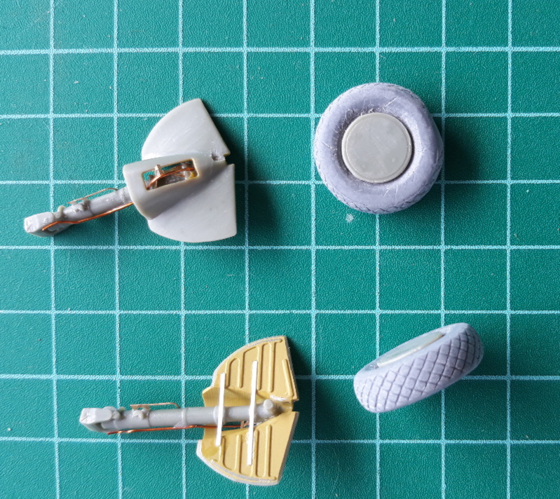
Finally, it should be noted that operational RAAF Vengeance II aircraft were fitted with treaded tyres. Those supplied in the kit are smooth. Maybe some enterprising manufacturer will make some in the near future, (how about it, Red Roo?), but I had to resort to the spares box again. The main wheel on the Vengeance was 36" diameter and a quick search revealed this was a not uncommon diameter on US aircraft, e.g. P-35 (36"x13"), P-38 (36"x12"), F7F (36"x11"), and B-25 (36"x17"). The F7F was the best match for width, and the tyres had a diamond pattern tread. I must have done something right, as all the stars aligned, and I found that I had a set of Cutting Edge F7F wheels in the spares box. OK, they were spoked and I would have to modify them to fit the hub fairing that was on the Vengeance but that would be easier than trying to put treads on the kit wheels.
Finishing and Painting:
I elected to finish my model as A27-220, GR-A, at Tsili Tsili. As you will note from my comments above, I was not in entire agreement with Dora Wing's version of the camouflage colours and the markings as supplied on the decals. I painted the model in a green and brown upper surface camouflage that I thought was closer to the US applied paints, and painted the under surface in a 'Sky Gray' colour, (or should that be color?), as I have found no evidence that the RAAF re-painted these aircraft in RAAF Sky Blue on arrival. The White leading edges and empennage were applied when the squadron moved forward to New Guinea.
I used the kit roundels and fin flash, (6 and 7) on the decal sheet, but made my own squadron codes, as I believe that these were Medium Sea Grey, not Sky Blue. The stores' number was made up from a Kiwi Wings sheet. I found some mission symbols from the spares box. I used the Pluto artwork from the decal sheet, and cut the 'Mustapha' into several pieces so that I could give it the curved appearance that is evident on the model. The style of the letters is not correct, but small enough to not be noticeable.
I wanted the model to depict the aircraft not long into its deployment to Tadji, so I only added a few mission markings and kept the weathering to a minimum. I'm no good at weathering anyway, so stuck to the kiss principle - at least that's my excuse!
Rigging the aerial wires was an interesting exercise. I prefer to use the nylon filaments extracted from a silk printing screen as they can be stretched and are reasonably strong. The aerial wire system on the Vengeance is a bit complex and required some planning to get it right. I was glad I made the decision early to make a metal antenna mast. I was reasonably happy with the end result.
See the next page for images of Peter's completed model (Steve - Editor).

